Simulate Early, Simulate Often... In Rhino
An analysis of alpine ski construction using SnS Pro
Intro
To a skier standing at the top of a mountain, above a cliff, or in a steep chute, the load-bearing and deformation properties of an alpine ski are of extreme importance. Given the high-stakes environment of downhill skiing, the skier must be confident that the ski will be able to withstand the stress associated with high speeds, large g-forces, and an array of different loading conditions. This analysis aims to model multiple different ski designs and loading conditions using Scan and Solve in order to determine the optimal ski design. Scan and Solve operates in full 3-D on the original geometry, even for composites, eliminating the need for any dimensional reduction and meshing, which are expensive manual steps.
Background
The ski being modeled is a wide ski designed to be used in soft snow conditions. The ski is 186 cm long with a uniform thickness of 1 cm and a waist width of 12 cm.
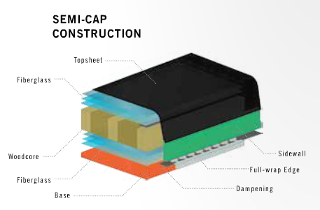
Two main variations of the ski will be studied: one entirely wooden ski and one ski with a wood core sandwiched by layers of fiberglass and a high-density polyethylene base. Both ski models have the same shape and differ only in their internal construction.
In the sandwich construction, each layer is 0.25 cm thick. For this project, the sandwich construction has been simplified to include only the polyethylene base, lower fiberglass layer, yellow poplar wood core, upper fiberglass layer, and acrylic binding plate. Each of these materials is helpfully stored in the material database of Scan and Solve.
One of the main focuses of this analysis is the effect of grain orientation on ski performance. Unlike polyethylene, fiberglass, and other isotropic materials, wood is orthotropic, meaning that it has a directionality associated with it. To examine the effect of grain orientation on ski performance, each model will be tested with the wood grains running along the length of the ski, as well astransverse to the length of the ski. Scan and Solve provides the ability to specify curved grain direction, a must for our profiled ski design. More information on setting grain direction can be found in the video tutorial and blog post. The resulting grain directions are shown below. The red arrows represent lengthwise grain direction, the green shows radial grain direction, and the blue arrows identify the thickness direction.
Left: A ski with grains lengthwise along the ski Right: A ski with grains transverse to the length of the ski
Loading Scenario 1: The Carve
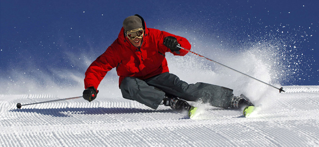
To simulate the forces anticipated while skiing, we can use loads and restraints in Scan and Solve to model real life loads. The first loading condition we will analyze is the turn, also known as carving.
A skier in the middle of a carved turn
When carving, the skier rotates the ski onto its edge and applies pressure to the binding plate, causing the ski to turn. A 2010 study published in the Scandinavian Journal of Medicine and Science in Sports explores the forces associated with a carved turn, accounting for ski deformation, edge penetration, and edge angle [1]. The study determined the vertical and horizontal reaction forces from the snow to be 840 N and 983 N, respectively. In the simulation, these surface loads were applied directly to the binding plate as vectors.
Left: Carving load applied to the binding plate Right: Carving restraint applied to the length of the ski
To restrain the model, the maximum edge penetration depth was set at 29.6 mm to simulate soft snow, and the entire length of the ski was restrained along the base in the x, y, and z directions. A guide for creating restraints can be found here.
After specifying grain direction, loading, and restraints, the simulation can be run. To determine the proper resolution, a convergence study was conducted. Displacement at a control point was plotted against resolution, and 160,000 was deemed to be an appropriate resolution.
Given Scan and Solve’s meshless operation, we can perform both coarse and fine analysis on the same geometry, eliminating the need to re-mesh and create a new solid model. The simulation was run for each construction design, and the results are as follows. Left: Displacement distribution under carving load Right: Stress distribution under carving load
In the images above, the ski is restrained along the right edge. The maximum displacement occurs at the middle of the ski on the opposite edge of the restraint, while the maximum stress is concentrated along the restrained edge.
Analysis of the table to the right shows that the ski designs with transverse wood grains minimize stress. To explain these results, it is necessary to examine the material properties of each component, found in the table below.
Given the orthotropic nature of wood, we must consider how the loads are distributed along each direction. The ultimate tensile strength (UTS) of yellow poplar is 155 MPa in its axial direction (along the grains) but only 3.7 MPa in the transverse direction. In this loading scenario, the designs with the grains oriented transverse to the length of the ski are able to bear the load along its grains, which leads to lower stresses. The designs with wood grains oriented along the length of the ski bear this load transverse to the grains, resulting in higher stresses.
An analysis of the displacement yields different results. The sandwich constructions experienced lower displacement than the all-wood constructions, which can be explained by the modulus of elasticity. Poplar has a high elastic modulus in the transverse bending direction, but its axial bending elastic modulus is two orders of magnitude lower, the smallest out of all the materials considered. This loading condition results in displacement along the length of ski as well as transverse to the length of the ski, causing less displacement in the sandwich constructions than the wood ones because of the isotropic layers, which have the same elastic modulus in all directions.
Loading Scenario 2: The Butter
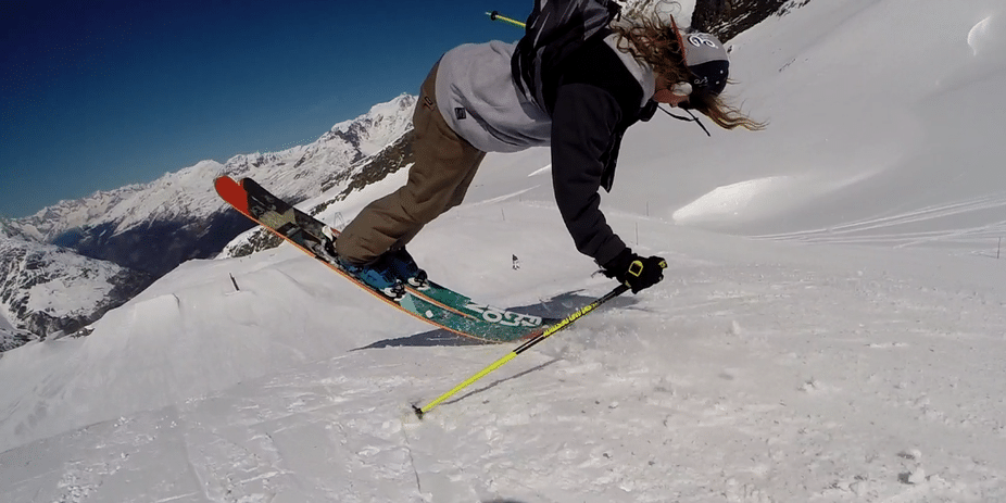
The next loading condition that we will analyze is the butter. A butter is a maneuver in which the skier simultaneously spins and applies pressure to the ski tips.
A skier performing a butter [i3]
Assuming a 170 lb skier applies his entire body weight to the tips of his skis at an 18 degree angle with horizontal, trigonometric calculations were performed to determine the horizontal and vertical loads experienced by the ski to be 185.85 N and 733.28 N, respectively. This load was applied to the front of the ski, ranging from the contact point with the snow to the tip. The binding plate was restrained in the x, y, and z directions.
When a skier skis over a bump, a reaction force is applied to the front of the ski in a similar manner. Provided a bump with an angle of 18 degrees with the slope above it and the same skier weight as the butter, this loading situation can also be considered a good model of a skier skiing over a bump.
Left: Butter loading applied to the front part of the ski Right: Butter restraint applied to the binding plate
The grain directions were specified, and the previous convergence study was used to determine resolution at 160,000. Each ski construction was simulated using this loading condition.
Left: Displacement distribution under butter loading Right: Stress distribution under butter loading
In this loading scenario, the lengthwise grain constructions reduce stress. In the lengthwise constructions, the load is carried along the grains, where the wood is stronger than any other material used in this design. As a result, the all-wood design is better at reducing stress in this loading condition than the sandwich construction. The transverse constructions have significantly higher stresses than the lengthwise constructions because almost all of the load is borne transverse to the grain direction, where the strength of the wood is very low.
A similar trend to the stress is observed in the displacement values. The all-wood, lengthwise construction had slightly lower stress than the lengthwise sandwich construction, but significantly lower displacement due to its high transverse elastic modulus.
Considering each construction’s performance in each loading scenario, the all-wood construction with lengthwise grains and the sandwich construction with lengthwise grains have the most promise. In order to provide measurements that can be compared to other models in the industry, an additional standardized loading scenario was simulated on these two models.
Loading Scenario 3: ASTM Standard Test Method for Linear Deformation and Breaking Strength of Alpine Skis
This test method is designed to provide an indication of a ski’s basic strength. One low friction roller restraint is placed on one end of the ski and a simple restraint that allows rotation but not displacement is placed on the other end. The two restraints are located 250 mm from each other, restraining only a portion of the ski, while the rest of the ski is free to deform [4]. Since the ski is of uniform thickness, we can choose any location on the ski to perform this test. In Scan and Solve, the roller restraint was modeled as a thin strip on the base of the ski, restrained only in the z direction. The simple restraint was modeled using an edge restraint in the x, y, and z directions. A vertical load is applied directly in the middle of the restrained area until failure.
Left: ASTM loads and restraints Right: Stress distribution in ASTM test
Since this is a test for breaking strength, the displacement is disregarded in this scenario. To determine failure, the stress observed in the ski was compared to the flexural yield strength of each material.
In the sandwich construction, failure first occurred in the top layer of fiberglass under a load of 4425 N. In the all-wood construction, failure occurred under a load of 1875 N. These results indicate that the sandwich construction has a greater basic strength than the all-wood construction, and the results can then be used to compare with other skis.
Skiing consists of constantly changing loading conditions, so while some models may perform better under specific loads, adequate performance is required under all conditions. Based on this analysis, the sandwich ski construction with grains oriented along the length of the ski is the overall best model at reducing stress and displacement.
This thorough analysis of ski constructions would not have been possible without Scan and Solve’s ability to easily guide wood fibers in an unconventional shape. The meshless, full 3-D operation resulted in quick and easy modeling and simulation of multiple models and loading conditions. These features of Scan and Solve allowed us to analyze a variety of different ski constructions and ultimately determine an ideal design so that skiers can continue to happily throw themselves down mountains without worrying about the structural integrity of their skis.
References
[1] D.Heinrich, et. al (2010). Calculation of the contact pressure between ski and snow during a carved turn in Alpine Skiing. Scand J Med Sci Sports, Vol 20, 485-492
[2] matweb.com
[3] http://www.wood-database.com/poplar/
[4] ASTM International. F780-93a(2012) Standard Test Method for Linear Deformation and Breaking Strength of Alpine Skis.
Images
[i1] https://static.evo.com/assetimages/features/4frnt/2014/4frnt-skis-s...
[i2] https://www.skiingacademy.com/wp-content/uploads/2017/04/Carve-Camp...
[i3] https://images.newschoolers.com/images/17/00/78/69/04/786904_926w_6...
Views: 2917
Comment


© 2024 Created by Michael Freytag.
Powered by
![]()
You need to be a member of Scan-and-Solve for Rhino to add comments!
Join Scan-and-Solve for Rhino