Simulate Early, Simulate Often... In Rhino
Analyzing Composite Materials in SnS Pro
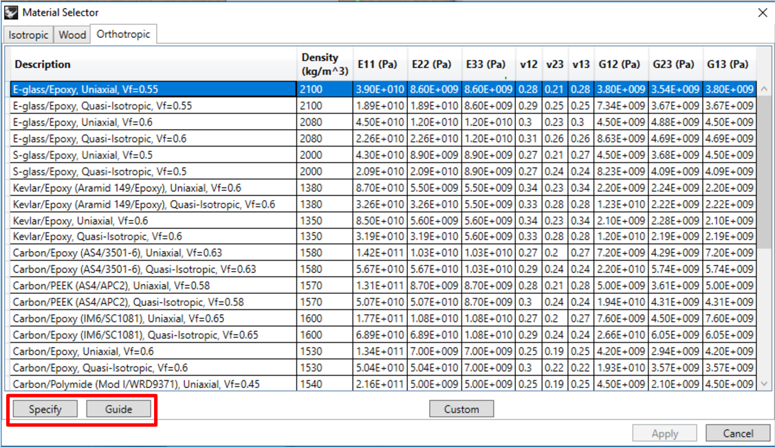
In Scan&Solve Pro, there are three primary types of materials to choose from: isotropic, wood, and orthotropic. Isotropic materials are things like metals that react the same when forces are applied from any direction. More details can be found here. Wood is a subset of orthotropic materials and has been covered here. The final category is composites, found under the “orthotropic” tab in SnS. This article will go over what makes a composite material, focusing on the creation of uniaxial and quasi isotropic composites, and how this is applied in Scan&Solve.
To understand why SnSPro asks for certain inputs, first it’s needed to know how composites are made. Most composites are made of multiple layers, or plies. Each ply consists of multiple fibers pointing in one direction, giving the ply an orientation (illustrated in the figure below[1], [2]).


In theory, ply orientations can be chosen arbitrarily, but only some ply configurations are manufacturable by the current technology. Two of the commonly used configurations are i) uniaxial and ii) quasi-isotropic, which are also supported in SnSPro.
Uniaxial Composites: Uniaxial composites are generally chosen when the loading of the object is known to be in one direction. Since the material properties along the fiber are stronger than in transverse directions, the fiber are laid in the direction of the load. When using plies, all the plies are laid such that they have the same orientation (figure below), which is the the direction of the loads as well.
Quasi-isotropic Composites: In quasi-isotropic composites, fiber are aligned in a way that all directions (in the plane) have identical load carrying capacity (stiffness). Quasi isotropic materials are generally chosen when the loading of the object is unknown. Since there is no clearly defined fiber, the “average” of the layers will act equally strong in plane. There are several such ply configurations, and two of the most commonly used configurations are plies stacked up in 0, -45, 45, 90 sequence and 0, -60, 60 sequence[1] with symmetry (angles in degrees). For example, in the image above, the fibers are oriented at 0, 45, 90, and -45 degrees with the ply oriented on the x axis for reference. This is important in manufacturing because it prevents warping.
The net effect of the stacked plies is that the composite on the left (uniaxial) will have different properties in the x (fiber) direction than in the y and z directions. On the right, the quasi isotropic composite doesn’t have a clearly defined axis, and as such, the x and y directions will act the same, with the z direction having different properties.
Specifying Composites in Scan and Solve Pro:
Above concepts are important to understand in order to correctly specify material directions in Scan and Solve Pro. We have provided two ways to specify orientation of fibers in composites: specify and guide. Note that we only have uniaxial and quasi-isotropic composite configurations (more complex configurations will be supported in future versions).
Specify: The specify option ask the user to choose an origin, a longitudinal direction, and a thickness direction. If a uniaxial material was chosen, the longitudinal direction will be the direction of the fiber. It is vital to understand that if uniaxial composites are chosen, the curve will be the direction of highest stiffness. If a quasi isotropic material was selected, the thickness direction will give the direction the plies are stacked.

Figure: specify would be best for green, guide would be best for blue
Guide: The guide option is more general and is better if a more complex direction of fiber is needed. When using guide option, the user is asked to specify a curve and a surface. The curve defines the fiber direction and the surface (normal) defines the thickness direction. Note that, when creating the model, the user needs to create a curve and a surface for each composite object they will need.
In conclusion, composite materials are made of layers (or plies) that are stacked on each other. Because composites are anisotropic, they behave differently in different directions. To specify the orientation of the plies in SnSPro, the specify and guide options must be used. The key is that the longitudinal direction or the curve specifies the direction of the fiber in a uniaxial composite and the thickness or surface prompts define the direction the plies are stacked on each other. For more information on the application of composite materials in Scan&Solve, check out the video here.
Reference:
[1] https://www.faa.gov/regulations_policies/handbooks_manuals/aircraft...
[2] https://fugahumana.wordpress.com/2012/07/03/an-introduction-to-comp...
Views: 2480
Comment


© 2024 Created by Michael Freytag.
Powered by
![]()
You need to be a member of Scan-and-Solve for Rhino to add comments!
Join Scan-and-Solve for Rhino